Each design project is unique, but the process of design here at Moss follows a well defined path.
Here’s how we approach a design project, from Program, and Field Measuring, through Schematic Design, Design Development, and Construction Documentation and on to Permits and Construction Administration.
This series of posts will explore our approach to the design process and give you an idea of how we might handle a future project of yours.
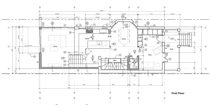
Here’s a floor plan: What are all of these symbols for?
As we’ve done in our recent post series on the design process, we will demonstrate all of these symbols using a floor plan from a recent project, the main level of a remodeled house on Carmen Ave. It shows the basic layout of the new space: walls, room names, some furniture and plumbing fixtures. But it is also covered with mysterious-to-the-layperson annotations. What do they mean? Why do we use them?
We use all these tags and symbols for two important reasons.
First, if every annotation were included in full on the floor plan, it would be so covered in information that none of it could be understood.
Additionally, during the course of a project small changes and additions of information are inevitable. When those changes are made, they need to be made consistently throughout the drawing set to avoid conflicts.
So … in an ideal drawing set there is only one endpoint for each piece of information. Each dimension, product specification, or construction note should provide a clear answer to a contractor trying to understand it.
Elements of an Architectural Drawings Set
Every architect uses symbols like these (although there can be a variation in their appearance from firm to firm) to designate the key information in their drawings. To a layperson, they can be a little confusing but they are VERY IMPORTANT when you’re trying to use a set of architectural drawings to visualize what your completed building will be like.
Here is our Field Guide to the Signs and Symbols of Architectural Drawings:
Keynotes

These square-enclosed numbers always refer to the numbered list of notes running down the right hand side of the same page they appear on. There is a new set of keynotes (starting from 01) on nearly every page in the drawing set. Often the keynotes offer a simple explanation of a feature and then refer to another part of the drawing set for further reference.
Grid Lines
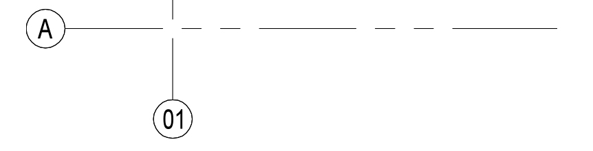
Grid lines don’t refer to any other pages in the set – they just help coordinate across the set showing where important elements line up with each other. Often, they are placed along structural lines to show how columns and bearing walls support the rest of the building. In the floor plan above they work that way; there is one at each exterior wall and at each internal structural line.
They also come in handy when referring to an area on the drawings to someone looking at their own copy in another location you can say “between grid lines B and C and 3 and 4” to localize a particular area.
Elevation Tags

This symbol denotes an elevation (drawing of a vertical surface in a building) located on another page. The inside of the circle tells you what page in the drawing set to go to, the number next to the arrow lets you know which drawing on the page it will be. The arrow points to the wall (interior or exterior) that will be shown in that elevation drawing. This symbol can come with multiple arrows and drawing numbers attached, pointing in several directions.
Section cuts

Section cuts (drawings of a slice of the building cutting through walls and structure) are also shown on other sheets. The sheet number is shown below the line and (when there are multiple section drawings) the number of the section is shown above. The turned down line at the right shows the direction that the section cut will “look.”
Door and Window Tags
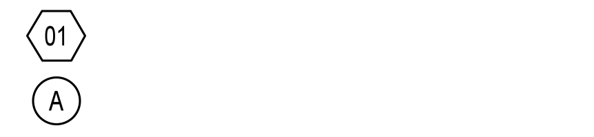
The door and window tags refer to numbered and lettered lists of product information on the Schedules sheets. By convention, the window tags are enclosed in hexagons, and numbered, and the door tags are enclosed in circles and lettered.
These numbers and letters refer to detailed spreadsheets of information on the “Schedules” sheets. For each unique type of door and window (exact duplicates share the same tag), the schedules list the specific dimensions for each window and door, the materials, the type of glass, the hardware and any other notes.
Wall Type Tags

Wall types allow us to designate on the plan how every wall will be constructed and what the existing walls are made of, without taking up much space on the main floor plan. The tags lead to the Wall Types Sheet, which follows the other Schedules sheets, and shows an annotated wall section for each type of wall.
Putting Symbols to work in your Architectural Drawings
If you’d like to see examples of the sheets referred to in this post – Sections, Elevations, Schedules, etc – check out our Tuesday post on Construction Documents. Or, come on down to Moss HQ and hire us to design a building for you, we’d be happy to create a building design to showcase all these symbols and give you an opportunity to practice reading an Architectural Drawings Set.